APPLICATIONS
FOR ELECTROTECHNICS
The system is designed for setting up bus-bar systems with rated currents up to 5 000 A and short-circuit strength up to 200 kA.
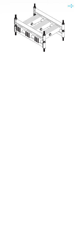
The body of the DELTA bus support is made of high-strength plastics based on glass fiber-reinforced polyester composites. The rigid support enables vertically oriented copper or aluminium conductors 10 mm thick to be perfectly fixed at a spacing of 120 mm. Two metallic bolts M10 thread are provided to tighten the supports and fastening them to the structure. The DELTA bus-bar support is manufactured either in the three-groove design to carry three conductors in phase, – this is Type DELTA 310 – or in the two-groove or single-groove design, types DELTA 210 and DELTA 110, respectively. The product features a high mechanical, electrical and thermal strength.
The density and arrangement of the DELTA bus supports should be such that the static bending load of a support due to the gravity of the system and the dynamic tensile load of the support due to short-circuit current will not exceed the permitted limits. The recommended densities of the mounted
bus-bar supports with their spacing (X) are given on the following pages in order to facilitate and simplify the design. This spacing respects the mechanical properties of the entire system during static as well as dynamic load. The data are usable provided that the following basic qualitative requirements are complied with by the manufacturer when mounting the product:
DELTA Series bus-bar supports conform to the requirements of technical standards and regulations – TP 2002103, ČSN EN 6060243-1/99, ČSN EN 60695-2-11/01. The product has been certified by EZÚ, Pod Lisem 129, 171 02 Praha 8, Czech Republic.
Prowatt s.r.o.
Teplická 309, 753 01 Hranice
Czech Republic
Company ID: 08670986
VAT number: CZ08670986
Phone: +420 776 170 063
E-mail: prowatt@post.cz
www.prowatt.cz